
Introduction
Framework and Methodology
Example
Resources
Collaborations
Introduction
AutomationML (AML) is an emerging standard in the automation domain to represent and exchange artifacts between heterogeneous engineering tools used in different disciplines, such as mechanical and electrical engineering.
The Systems Modeling Language (SysML) is a modeling standard influenced by software modeling languages, like UML, typically adopted in the early phases of the engineering process from requirements specification to architecture modeling.
We investigate the commonalities and differences concerning the structural modeling parts of AML and SysML in support of establishing tool-independent interoperability between early system modeling phases based on SysML and discipline-specific design phases based on
AML.
This support for cross-disciplinary modeling is facilitated by a bridge between AML and SysML built on model-driven interoperability techniques.
Framework and Methodology
We provide a cross-disciplinary integration chain for AML and SysML based on model-driven interoperability techniques (metamodeling, UML/SysML profiling, model transformations).
The stereotypes of the AML4SysML profile are listed in Table 1 and depicted in Figure 1. It comprises 16 stereotypes and covers almost the whole CAEX_IEC_62424 standard.
The AML stereotypes are grouped in 4 sets, namely, libraries, classes, objects, and relationships. All of the stereotypes extend UML metaclasses from the UML language units Classes (including the metaclasses Package, Generalization, Association, and Dependency) and CompositeStructures (Class, Port, and Connector). These language units are shared also by the SysML standard (UML4SysML).
AML objects IH and IE and AML classes IC and SUC can be modeled as SysML blocks, which allow to model systems as trees of modular components representing the specification of software, hardware, or human elements on SysML Block Definition and Internal Block Diagrams.
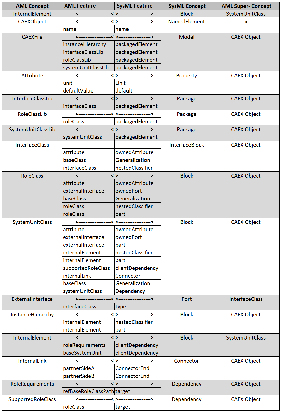
Table 1: Mapping AML with SysML by Profiling.

Figure 1: Overview of the AML4SysML Profile.
Our framework offers the following benefits:
– The proposed mapping between AML and SysML aims at promoting a cross-fertilization between these two standards and their communities. Because of the achieved mapping, on the one hand the AML community may benefit from the graphical representation brought by SysML diagrams, from model-based techniques and tools for SysML and UML. On the other hand, the SysML community is able to use extensive AML libraries for modeling production systems, such as the ones defined by the AML standard to mention just a few cross-fertilization possibilities.
– The transition from high-level systems models to domain-specific design models is now enabled. The mapping provides the basis to bridge the gaps in current tool chains which employ both modeling standards. For instance, by mapping SysML models to AML models, engineering tools applied in mechanical and electrical engineering relying on AML as data exchange format may process the system definition captured by SysML models.
– The correspondences used to integrate both languages ensure traceability and propagation of results between the different tools which may be exploited by requirements engineering tools as well.
Example
The IAF of the Otto-v.-Guericke University Magdeburg production system (cf. Figure 1) consists of a set of turntables, conveyors and motors. It is wired,
using a modular fieldbus I/O system (WAGO) including a coupler and several digital I/O modules, to Raspberry Pi based controllers. These controllers host the software that controls the aforementioned plant components.
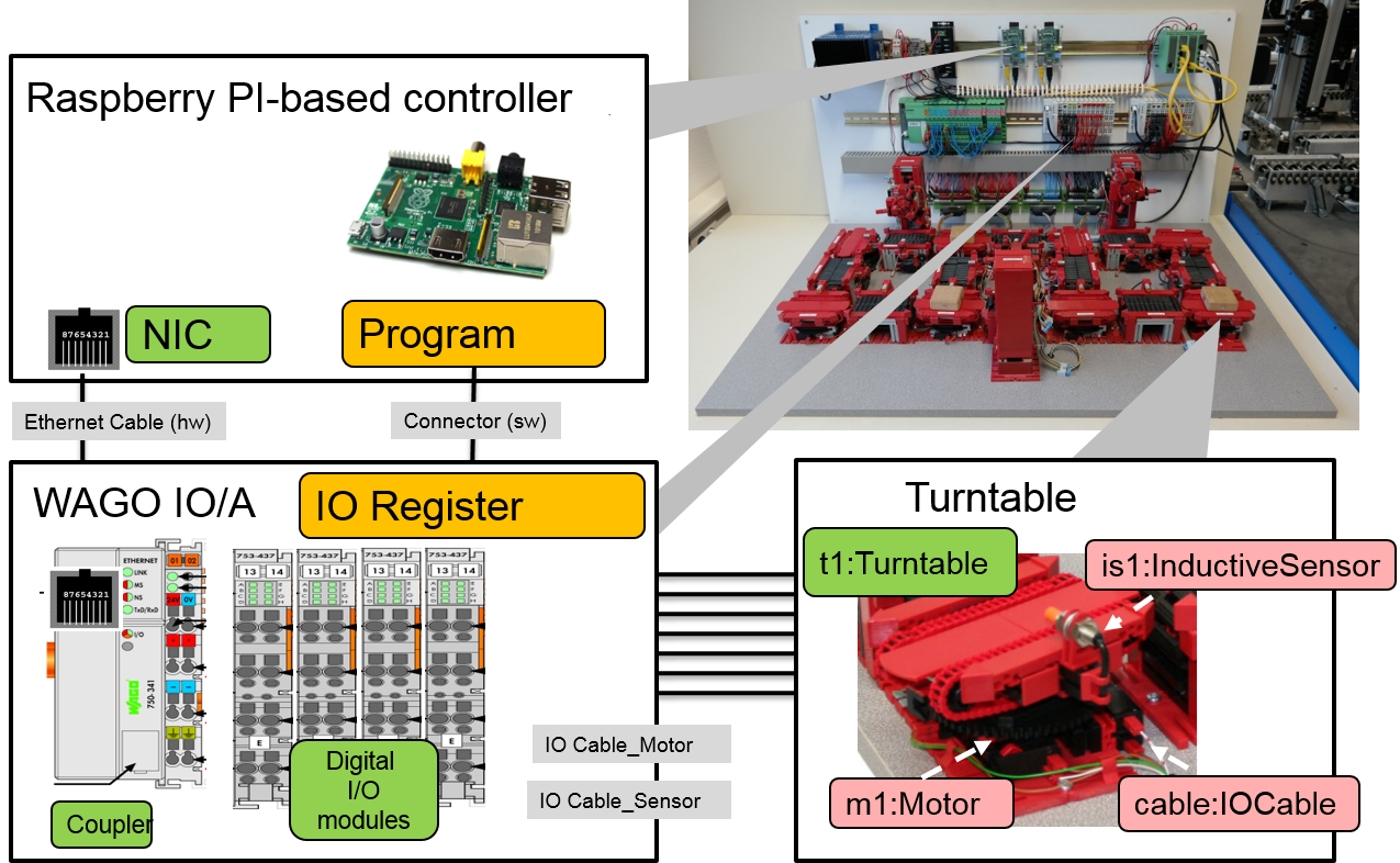
Figure 1: IAF Case Study.
Figure 3 shows the AML model of a lab-sized production system hosted at IAF of the Otto-v.-Guericke University Magdeburg

Figure 3: IAF Case Study AML model created using the default AML Editor.
Thanks to SysML, the same production system can be modeled in SysML and its content shown on Block Definition Diagrams and Internal Block Diagrams. The tree-based structure of AML artifacts can be retained in SysML and, in addition, the same model element can be shown on multiple diagrams with customized concrete syntax. In Figure 4, the Project Browser shows the AML Model as Packages and SysML Blocks. A Block Definition Diagram (on the left) can be created and displayed using a SysML-specific toolbox and concrete syntax.
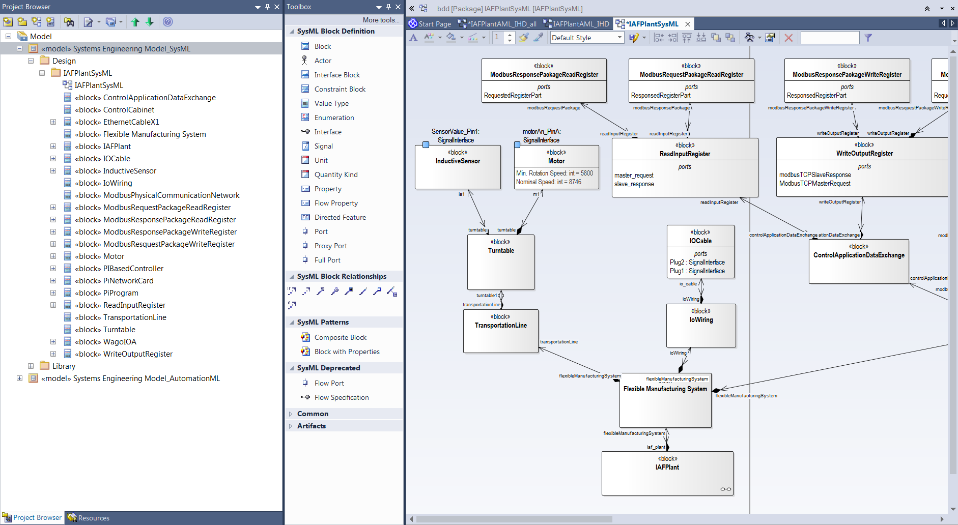
Figure 4: IAF Case Study in SysML usin the Enterprise Architect(r) modeling environment.
The same SysML model annotated with stereotypes of the AML4SysML profile can be created with AutomationML Engineer for Enterprise Architect, a plugin for the modeling tool Enterprise Architect (EA). It enables importing and exporting of AutomationML data and reuse the EA graphical capabilities for editing and visualizing AutomationML-models (demo videos are available here).
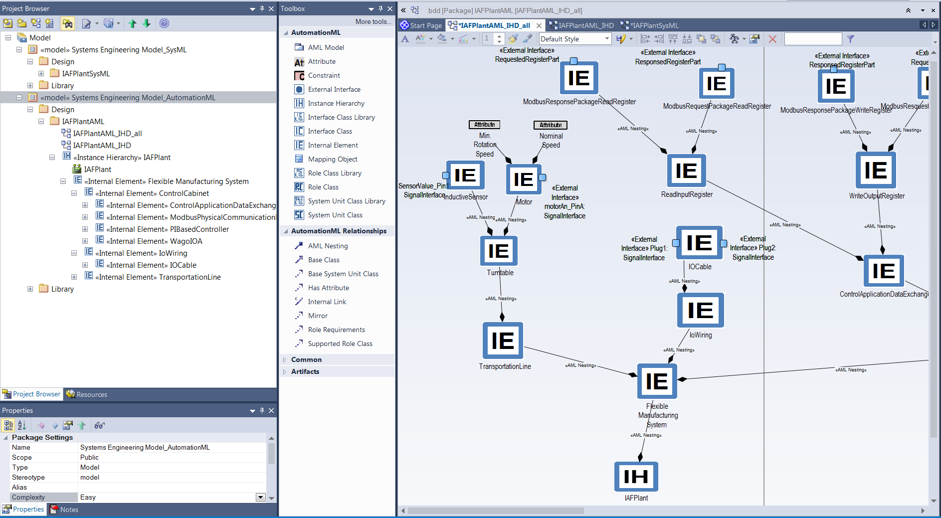
Figure 5: IAF Case Study created with AutomationML Engineer for Enterprise Architect.
In Figure 5, the Project Browser on the left shows the content of the IAF AML Model in the usual hierarchical tree view mode (cf., the InstanceHierarchy tab in Figure 3). Its content can be now edited and displayed on AML-specific diagrams. In particular, the Figure 5 lays out the IAF Plant Instance Hierachy on a Instance Hierarchy Diagram (IHD) corresponding to the SysML BDD shown in Figure 4.
The content of IHDs can be edited through a AML-specific toolbox. It is worth noting that the AML Model (i.e, the tree-based content shown in the Project Browser) can displayed on a arbitrary number of diagrams. In Figure 6, a SysML BDD and a AML IHD diagrams display a partial view of AML Model, i.e., a Turntable Block/IE, its inner elements, Motor and InductiveSensor Blocks/IEs, and their Features/Attributes. The user can then decide to delete an element (e.g., the Motor Block/IE) from a specific diagram or from the whole model, i.e., from the tree. In the latter case, the editor takes care of keeping all the diagrams synchronized by removing the corresponding shapes, including containment relationships, from diagrams.
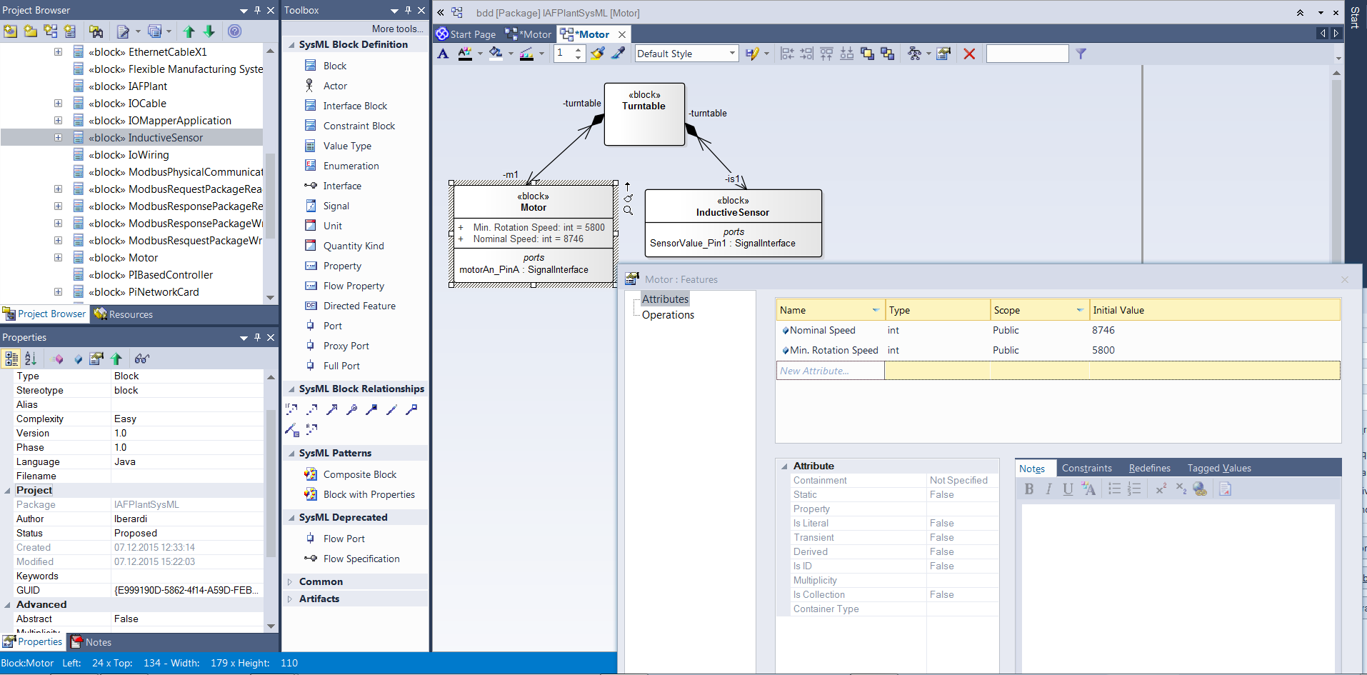
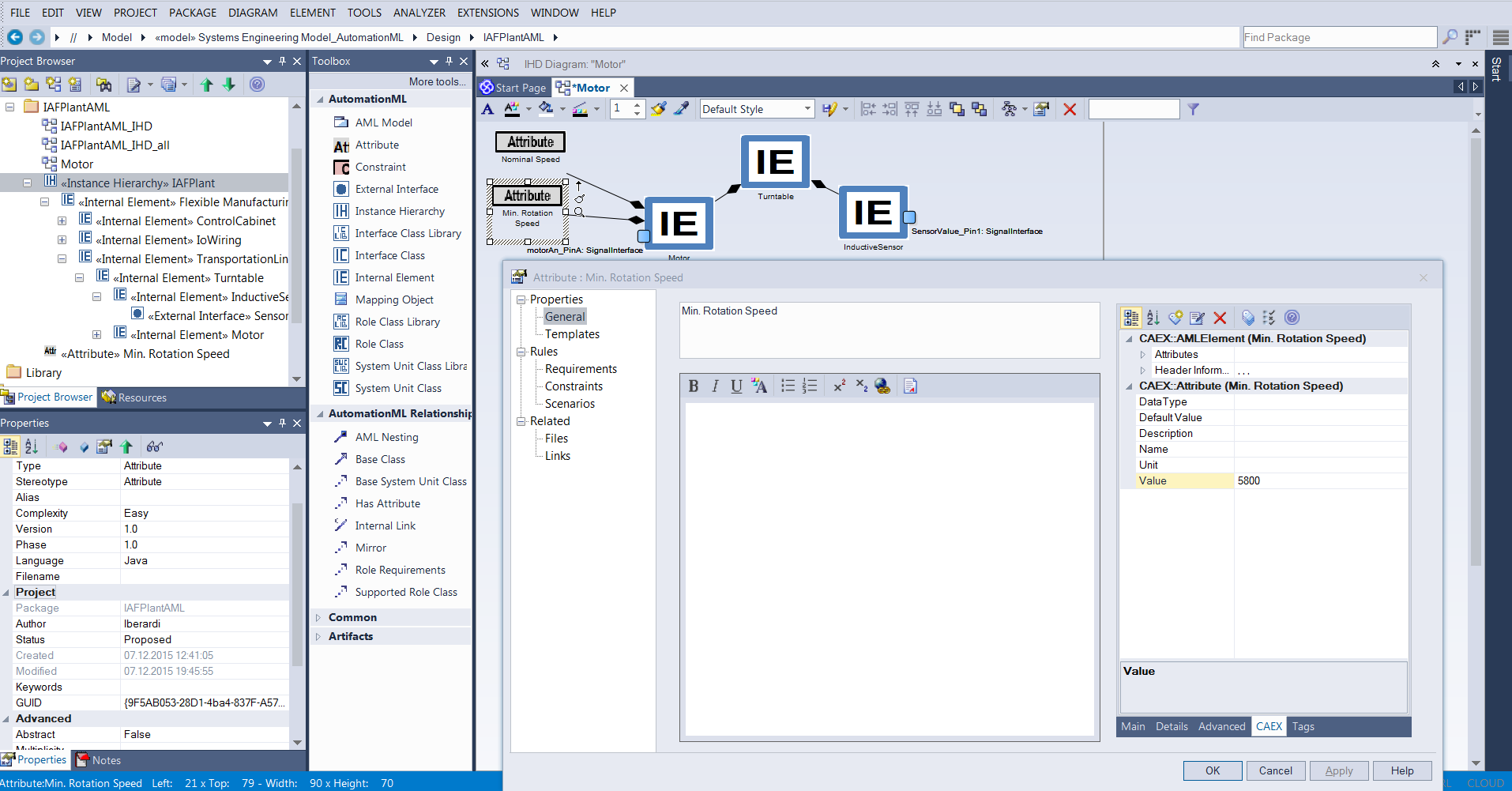
Figure 6: Editing a Turntable element as a SysML Block on a BDD and as an InternalElement on a IHD.
AML Classes (SUC, RC, IC) and Objects (IE, ExtI see Table 1) can then be identified and AML Relationships established among them. As a result a graph of AML Classes and Objects can be displayed on a single BDD (see Figure 7) or suitably split in multiple ones.
Resources
Please find the following artefacts at our Git Repositories:
- AML metamodel
- AML Profile for Enterprise Architect and for XMI-compliant tools
- Ecore model of IAF Case Study
- AML2SysML transformation (Eclipse ATL Project)
- SysML2AML transformation (Eclipse ATL Project)
- Eclipse Installation Instruction for AML2SysML and SysML2AML trasformations execution
In collaboration with
| Christian Doppler Laboratory Software Engineering Integration for Flexible Automation Systems | Institute of Ergonomics, Manufacturing Systems and Automation (IAF), | LieberLieber |
|---|---|---|
|
|
 |
 |